Bringing up an LCD screen on an AM335X
Introduction
I built a new board called guppy-buddy that looks like a game console using the Octavosystems OSD335X-SM which made the design process must simpler than if I attempted to layout an entire processor, PMIC and RAM as well as everything else I wanted to do.
One aspect of the board that I had some trouble with was bringing up the Newhaven 5inch LCD Screen to work with the parallel LCD interface. Out of all things I thought that it would not have been this difficult. There were already reference designs online as well as documentation within the kernel describing how everything hooks up but due to hardware design caveates and mistakes on my part and quirks in the kernel boot process I didn’t understand it took a long time to get the LCD up and running.
Physical Signals
The AM3355x can connect up to a 16-bit or 24-bit LCD screen using the following signals:
- LCD_DATA[0 - 15][16 - 23]
- LCD_VSYNC
- LCD_HSYNC
- LCD_AC_BIAS_EN
- LCD_PCLK
- An optional enable signal from a GPIO
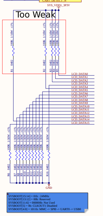
Besides driving the LCD panel, the LCD data signals are also used to configure the order in which the processor attempts to boot from devices. This Octavo Application Note explains it better than I could. As the application note states in the red box below the description the weak pullups/pulldowns might effect your design. In my case the LCD panel pulled the signals lower than the required upper voltage threshold and so my processor would not boot when the LCD panel was plugged in. In order to fix this issue I changed my pull-up resistors to 10K instead of 100K.
Another nasty surprise
Right before fabricating the board, I realized that my connector had the contacts on the wrong side (bottom instead of top) so I wouldn’t be able to rotate the LCD screen to face me when it was plugged into the board so I changed the part number of the flat flex connector to use the pins on the other side (this should have been a glaring red flag!). Unfortunately, I didn’t flip the signals to go in the reverse order. Effectively rendering all my pins flipped 1 -> 40 and 40 -> 1. I was able to work around this by purchasing an FFC cable extender from Adafruit as well as an FFC cable that had connectors on one side on one end and the other side on the other end.
DTS
I wrote a DTS file to configure the kernel to adapt to my board and used, as reference, TI’s Evaluation Module and the Beaglebone 5 Inch LCD cape. Here is the relevant portion of the DTS file:
/****************************************************************************
* LCD Control
****************************************************************************/

/ {

  lcd_backlight: backlight {
    status = "okay";
    compatible = "gpio-backlight";
    pinctrl-names = "default";
    pinctrl-0 = <&backlight_pin>;
    gpios = <&gpio2 2 GPIO_ACTIVE_HIGH>;
  };

  lcd0:panel {
    status = "okay";
    compatible = "ti,tilcdc,panel";
    pinctrl-names = "default";
    pinctrl-0 = <&lcd_pins>;
    enable-gpios = <&gpio1 20 0>;
    backlight = <&lcd_backlight>;

    panel-info {
      ac-bias           = <255>;
      ac-bias-intrpt    = <0>;
      dma-burst-sz      = <16>;
      bpp               = <16>;
      fdd               = <0x80>;
      sync-edge         = <0>;
      sync-ctrl         = <1>;
      raster-order      = <0>;
      fifo-th           = <0>;
      invert-pxl-clk    = <1>;
    };

    display-timings {
      native-mode=<&timing0>;
      timing0: 800x480 {
        clock-frequency = <45000000>;
        hactive         = <800>;
        vactive         = <480>;

        vsync-len       = <3>;
        vfront-porch    = <13>;
        vback-porch     = <32>;

        hsync-len       = <48>;
        hfront-porch    = <40>;
        hback-porch     = <88>;


        hsync-active    = <1>;
        vsync-active    = <1>;
        de-active       = <1>;
        pixelclk-active = <1>;
      };
    };
  };
};

&lcdc {
  status = "okay";
  blue-and-red-wiring = "straight";
};

&am33xx_pinmux {
  backlight_pin: backlight_pin_default {
    pinctrl-single,pins = <
      AM33XX_IOPAD(0x890, PIN_OUTPUT_PULLDOWN | MUX_MODE7 ) /* (R7) gpmc_advn_ale.gpio2[2] (BACKLIGHT PWM) */
    >;
  };
  lcd_pins: lcd_pins {
    pinctrl-single,pins = <
      AM33XX_IOPAD(0x8a0, PIN_OUTPUT          | MUX_MODE0 ) /* (R1) lcd_data0.lcd_data0 */
      AM33XX_IOPAD(0x8a4, PIN_OUTPUT          | MUX_MODE0 ) /* (R2) lcd_data1.lcd_data1 */
      AM33XX_IOPAD(0x8a8, PIN_OUTPUT          | MUX_MODE0 ) /* (R3) lcd_data2.lcd_data2 */
      AM33XX_IOPAD(0x8ac, PIN_OUTPUT          | MUX_MODE0 ) /* (R4) lcd_data3.lcd_data3 */
      AM33XX_IOPAD(0x8b0, PIN_OUTPUT          | MUX_MODE0 ) /* (T1) lcd_data4.lcd_data4 */
      AM33XX_IOPAD(0x8b4, PIN_OUTPUT          | MUX_MODE0 ) /* (T2) lcd_data5.lcd_data5 */
      AM33XX_IOPAD(0x8b8, PIN_OUTPUT          | MUX_MODE0 ) /* (T3) lcd_data6.lcd_data6 */
      AM33XX_IOPAD(0x8bc, PIN_OUTPUT          | MUX_MODE0 ) /* (T4) lcd_data7.lcd_data7 */
      AM33XX_IOPAD(0x8c0, PIN_OUTPUT          | MUX_MODE0 ) /* (U1) lcd_data8.lcd_data8 */
      AM33XX_IOPAD(0x8c4, PIN_OUTPUT          | MUX_MODE0 ) /* (U2) lcd_data9.lcd_data9 */
      AM33XX_IOPAD(0x8c8, PIN_OUTPUT          | MUX_MODE0 ) /* (U3) lcd_data10.lcd_data10 */
      AM33XX_IOPAD(0x8cc, PIN_OUTPUT          | MUX_MODE0 ) /* (U4) lcd_data11.lcd_data11 */
      AM33XX_IOPAD(0x8d0, PIN_OUTPUT          | MUX_MODE0 ) /* (V2) lcd_data12.lcd_data12 */
      AM33XX_IOPAD(0x8d4, PIN_OUTPUT          | MUX_MODE0 ) /* (V3) lcd_data13.lcd_data13 */
      AM33XX_IOPAD(0x8d8, PIN_OUTPUT          | MUX_MODE0 ) /* (V4) lcd_data14.lcd_data14 */
      AM33XX_IOPAD(0x8dc, PIN_OUTPUT          | MUX_MODE0 ) /* (T5) lcd_data15.lcd_data15 */
      AM33XX_IOPAD(0x8e0, PIN_OUTPUT          | MUX_MODE0 ) /* (U5) lcd_vsync.lcd_vsync */
      AM33XX_IOPAD(0x8e4, PIN_OUTPUT          | MUX_MODE0 ) /* (R5) lcd_hsync.lcd_hsync */
      AM33XX_IOPAD(0x8e8, PIN_OUTPUT          | MUX_MODE0 ) /* (V5) lcd_pclk.lcd_pclk */
      AM33XX_IOPAD(0x8ec, PIN_OUTPUT          | MUX_MODE0 ) /* (R6) lcd_ac_bias_en.lcd_ac_bias_en */
      AM33XX_IOPAD(0x850, PIN_OUTPUT_PULLUP   | MUX_MODE7 ) /* (R14) gpmc_a4.gpio1[20] (LCD EN) */
    >;
  };
};
At the moment the backlight doesn’t have any ‘levels’ it’s just on or off, this is something that I’ll have to add in the future.
Kernel Boot
I ran into a strange issue where the LCD wouldn’t work. Upon further inspection the /dev/fb0 didn’t load. Looking into this even further I found that the kernel module that manages the display sub system is called DRM or Direct Render Manager. This module will attach display controllers to display outputs. In my case the Texas Instrument’s LCD Controller (TILCDC) and the panel. The kernel would load the DRM, then it would load TILCDC controller and finally the panel afterwards. Unfortunately the TILCDC checks if there is a panel or device to use within the ‘tilcdc_init’ function and if it is not in there then it doesn’t create a new frame buffer. Because the panel was loaded after the controller, the controller doesn’t see it and doesn’t load it. Here is the relevant boot messages:
...
[    2.056859] [drm] Initialized vgem 1.0.0 20120112 for virtual device on minor 0
[    2.064449] usbcore: registered new interface driver udl
[    2.071783] OF: graph: no port node found in /ocp/lcdc@4830e000
[    2.077961] OF: graph: no port node found in /ocp/lcdc@4830e000
[    2.084831] tilcdc 4830e000.lcdc: Check if componentized
[    2.090258] tilcdc 4830e000.lcdc: Not componentized
[    2.095191] tilcdc 4830e000.lcdc: Look for remote node
[    2.100384] OF: graph: no port node found in /ocp/lcdc@4830e000
[    2.106356] tilcdc 4830e000.lcdc: Return 0!
[    2.110583] tilcdc 4830e000.lcdc: no encoders/connectors found, failed to initialize
...
[    2.713767] panel panel: found backlight
...
[    2.745671] panel panel: found enable GPIO
...
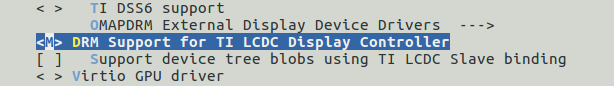
To work around this issue I modified the kernel so that the TILCDC was loaded as an external module while keeping the panel as a built in module.
here is the full discussion on the beagleboard.org message board. Thanks to Andrew Pikul for giving me some ideas.
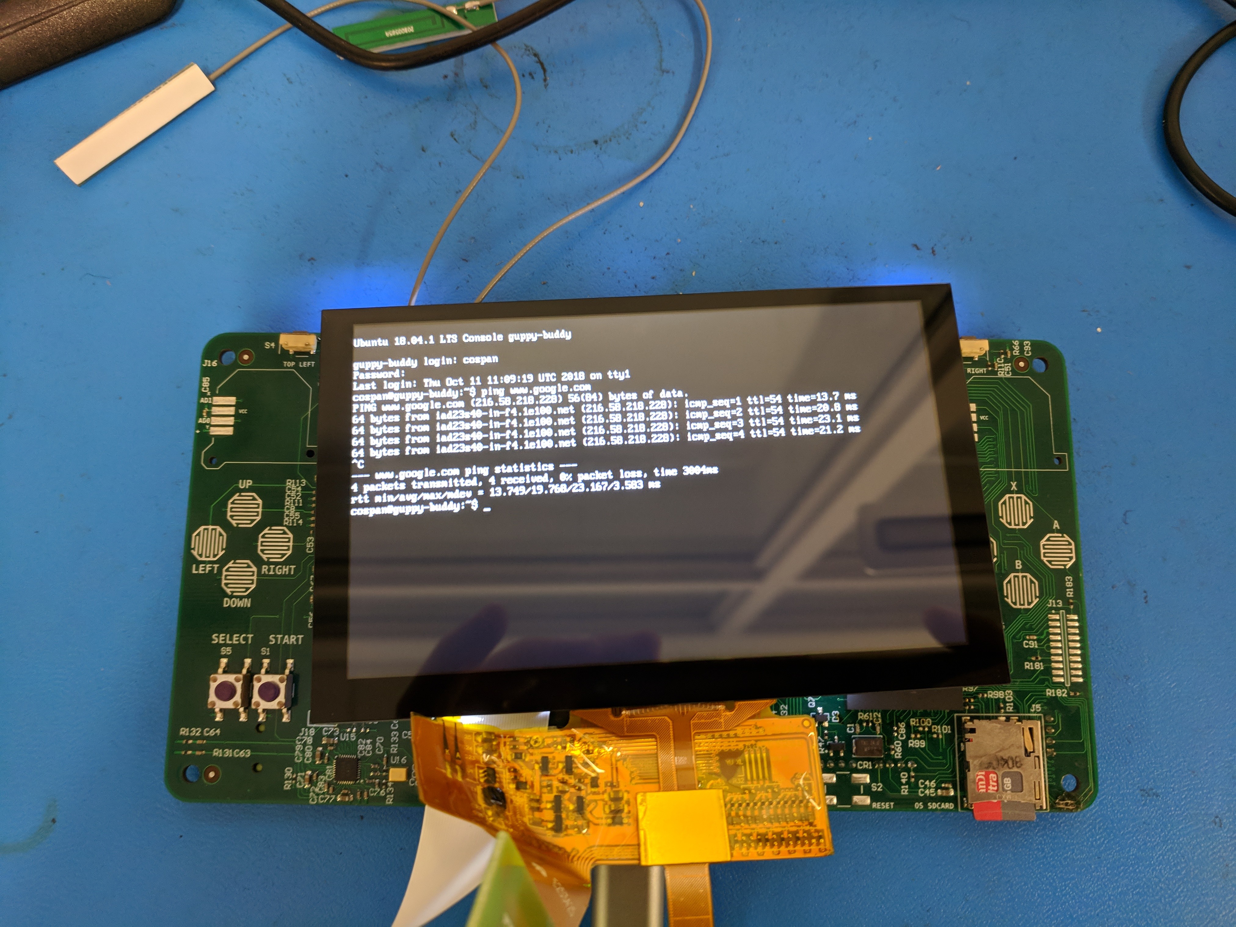
Finally, here is the board booted with an LCD screen: