Raspberry Pi Camera on TX2
Description
First, I’m not an expert, I learned a lot by reading and hacking on this so there may be misunderstanding on my part and if you find something that I did wrong please let me know. I’ve got a few requests on how to bring up the Rapsberry Pi camera on the TX1/TX2 and I want to help you out. So here how I did it.
Obligatory Intro
Configuring the TX2 to interface with Raspberry PI cameras opens up the possiblity for low cost camera applications. Unfortunately there are very few boards that have Raspberry Pi Camera connectors. Auvidea is the only company that comes to mind.
The following are the steps I used to support multiple Raspberry Pi cameras on one board.
Notes
It’s assumed the reader is familiar enough with the kernel build process and has already download the Nvidia driver package. At the time of this writing the L4T 28.1 Production Release was used. As long as the changes to all future updates are minimal then these instructions shouldn’t change much.
If not you can follow the instructions here on how to get the drivers download:
A VERY GOOD resource is the driver L4T Documentation, specifically the ‘Sensor Driver Programming Guide’, in fact this document should only serve as a rough example of how to do something.
I’ve also added files to bottom of this document if you wish to download them.
Overview
An overview of the whole process is as follows:
- Prepare the Device Tree Source.
- Configure the kernel.
- Modify the IMX219 Driver.
- Userland Tests
Preparing the Device Tree Source
There are two ways to modify the kernel.
- Kernel Configuration File: this will tell the kernel which features and drivers should be built. You can also specify what drivers should be packed into the kernel and which ones should be compiled but seperate from the kernel. As an example: We would modify this in order to tell the kernel to build in support for the IMX219 driver.
- Device Tree Source (DTS): This is how you can configure the kernel at boot to behave differently on one board vs another. As an example the Raspberry Pi and The Raspberry Pi Zero look very different but have the same kernel because there are two different DTS files for it.
We need to add support for the IMX219 camera (Raspberry Pi Model 2 Camera). Because there is no mechanism to recognize CSI cameras while the kernel is running we have to modify the DTS in order to tell the kernel how to recognize them. This is different from USB because USB has a standard mechanims that kernel can use to recognize when a new device is inserted.
Each board is configured with one final DT(B) (B)inary file. This DTB is a compiled version of the (S)ource DT(S) and the (I)ncluded DTS(I) files.
We need to configure the DTS file to recognize the IMX219 Camera. To do this we have to describe the following:
- Which CSI ports the cameras are attached to.
- How to configure the cameras using I2C.
- What modes the cameras have (Does it have 1920x1080 and/or 1280x720).
- How to configure the Video Input architecture of the TX2.
We can write a DTS file from scratch but for many applications you can use the default DTS file used for the NVIDIA devboards. If you want to get more fancy see the link above for how to port TX2 to a new platform.
The default configuration file for the TX2 devboard is
Linux_for_Tegra/sources/hardware/nvidia/platform/t18x/quill/kernel-dts/tegra186-quill-p3310-1000-c03-00-base.dtsThere is not much in this file because it takes most of it’s configuration from:
Linux_for_Tegra/sources/hardware/nvidia/platform/t18x/quill/kernel-dts/tegra186-quill-p3310-1000-a00-00-base.dtsIn the top of that file you will find:
#include <t18x-common-platforms/tegra186-quill-common-p3310-1000-a00.dtsi>
#include <t18x-common-platforms/tegra186-quill-power-tree-p3310-1000-a00-00.dtsi>
#include <t18x-common-platforms/tegra186-quill-camera-modules.dtsi>
#include <t18x-common-modules/tegra186-display-e3320-1000-a00.dtsi>

/* comms dtsi file should be included after gpio dtsi file */
#include <t18x-common-platforms/tegra186-quill-comms.dtsi>
#include <t18x-common-plugin-manager/tegra186-quill-p3310-1000-a00-plugin-manager.dtsi>
#include <t18x-common-modules/tegra186-super-module-e2614-p2597-1000-a00.dtsi>
#include <t18x-common-plugin-manager/tegra186-quill-display-plugin-manager.dtsi>
#include <t18x-common-prod/tegra186-priv-quill-p3310-1000-a00-prod.dtsi>
#include <t18x-common-plugin-manager/tegra186-quill-camera-plugin-manager.dtsi>

#include <dt-bindings/linux/driver-info.h>
Modify it to look like this:
To simplify the development of the camera connector I’m going to disable Nvidia’s clever camera plugin manager and remove all references to other camera boards.
#include <t18x-common-platforms/tegra186-quill-common-p3310-1000-a00.dtsi>
#include <t18x-common-platforms/tegra186-quill-power-tree-p3310-1000-a00-00.dtsi>
//#include <t18x-common-platforms/tegra186-quill-camera-modules.dtsi>
#include <t18x-common-modules/tegra186-display-e3320-1000-a00.dtsi>

/* comms dtsi file should be included after gpio dtsi file */
#include <t18x-common-platforms/tegra186-quill-comms.dtsi>
#include <t18x-common-plugin-manager/tegra186-quill-p3310-1000-a00-plugin-manager.dtsi>
#include <t18x-common-modules/tegra186-super-module-e2614-p2597-1000-a00.dtsi>
#include <t18x-common-plugin-manager/tegra186-quill-display-plugin-manager.dtsi>
#include <t18x-common-prod/tegra186-priv-quill-p3310-1000-a00-prod.dtsi>
//#include <t18x-common-plugin-manager/tegra186-quill-camera-plugin-manager.dtsi>

#include <dt-bindings/linux/driver-info.h>
Now we removed all references to the previous cameras we’re going to add two files. One that will configure the board level camera(s) and the other to configure the internal architecture of the TX2 Video Interface.
Create a new file ‘tegra186-my-camera-config-a00.dtsi’ to the following directory:
Linux_for_Tegra/sources/hardware/nvidia/platform/t18x/common/kernel-dts/t18x-common-platforms/Create a second file with the same name in the following directory
Linux_for_Tegra/sources/hardware/nvidia/platform/t18x/common/kernel-dts/t18x-common-modules/The ‘my-camera-config’ can be changed to whatever you want and the ‘a00’ is just the first version of this file.
At the moment I have been using the ‘platforms’ version of the file as a passthrough for the module but technically you can override the intended abstract ‘modules’ for some general platform but I’ve just kept the file in place for when I find a use for it. If you have some feedback on this I would love to hear it.
Inside the ‘platforms’ version of the file include the following line
#include <t18x-common-modules/tegra186-my-camera-config-a00.dtsi>Within the ‘modules’ file we need to configure the kernel to do the following:
- Make space for GPIOs for the
- Reset line(s)
- Possible GPIO I2C Multiplexer
- TX2’s host1x
- NVCSI Component: Configure the CSI lanes to talk to all the cameras correctly.
- VI: Configure the NVCSI output to either ISP or directly to memory.
- I2C: How to configure the camera to output the video you want.
- GPIOs
- Configure GPIOs to do certain behaviors such as reset the camera, power on or off the camera regulators.
- tegra-camera-platform
- Describes the physical location of the camera.
- Configure the ISP to process images.
- Describes other elements that make up a camera, such as a focuser.
To help visualize this I created a block diagram. This diagram doesn’t show the GPIOs as it is already pretty busy.
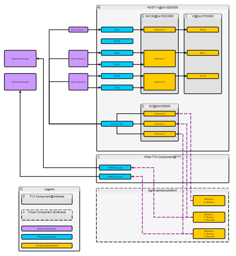
For our application I’ll configure the kernel to accept video from three seperate Raspberry Pi Cameras attached to ports A, C and E. It will look like this.
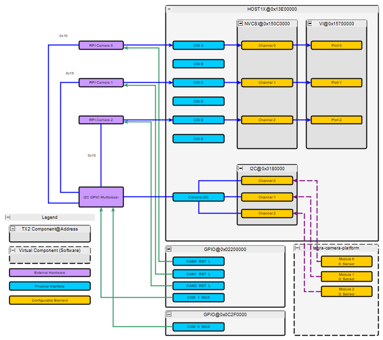
All of the Raspberry Pi cameras have the same I2C Address so we need a way to distinguish one camera from another. The easiset way is with a multiplexer. We’ll be using a GPIO multiplexer as the driver is already built into the kernel. One of the GPIOs for the multiplexer is on the AON processor so a second GPIO box is added for this.
At a high level the data from the purple Raspberry Pi cameras come into the TX2 through the blue CSI channels. We only need two lane CSI bus so we take CSI A, if we needed four lanes we would reserve two CSI blocks as shown in the top image. The NVCSI core will extract the raw image from the CSI protocol and send the data to VI. ‘Video Input’ is essentially a video router, it routes the video to either the ISP or directly to memory. If the Raspberry Pi camera had an internal Image Signal Processor to convert the image to a useful RGB image we would just tell the VI to route the image data to memory but because the camera does not have an ISP we use the ISP on the TX2. The process of routing the video data after the VI is done within userland when the kernel is booted up so we are done once the VI is attached correctly.
In the t18x-common-modules/tegra186-my-camera-config-a00.dtsi file add the following lines:
#include "dt-bindings/clock/tegra186-clock.h"
#include <dt-bindings/pinctrl/pinctrl-tegra.h>
#include <dt-bindings/gpio/tegra186-gpio.h>

#define CAM0_RST_L  TEGRA_MAIN_GPIO(R, 0)
#define CAM1_RST_L  TEGRA_MAIN_GPIO(N, 2)
#define CAM2_RST_L  TEGRA_MAIN_GPIO(R, 5)

#define CAM_0_MUX   TEGRA_AON_GPIO(V, 5)
#define CAM_1_MUX   TEGRA_MAIN_GPIO(X, 6)
The above adds includes for controlling pins, and clocks as well as the macros we use just below to configure our GPIOs defines.
The following will tell the kernel to reserve and configure the GPIOs. We’ve configured the GPIOs to be all outputs in the default low position.
/ {
  /* set camera gpio direction to output */
  gpio@2200000 {
    camera-control-output-low {
      status = "okay";
      gpio-hog;
      output-low;
      gpios = < CAM0_RST_L 0
                CAM1_RST_L 0
                CAM2_RST_L 0
                CAM_1_MUX  0>;
      label = "cam0-rst",
              "cam1-rst",
              "cam2-rst",
              "cam-mux1";
    };
  };
  gpio@c2f0000 {
    aon-camera-control-output-low {
      status = "okay";
      gpio-hog;
      output-low;
      gpios = < CAM_0_MUX 0>;
      label = "cam-mux0";
    };
  };
};
Now to configure the host1x interface. The Video Interface is a subblock of it:
Video Interface: We need to describe the number of channels that it will manage. Each channel needs an input and an output. The input with the ‘vi_inX’ label is where the output of the NVCSI is routed and the ‘vi_portX’ is where the user will have access to it.
/ {
  host1x {
    vi@15700000 {
      num-channels = <3>;
      ports {
        #address-cells = <1>;
        #size-cells = <0>;
        vi_port0: port@0 {
          status = "okay";
          reg = <0>;
          vi_in0: endpoint {
            status = "okay";
            csi-port = <0>;
            bus-width = <2>;
            remote-endpoint = <&imx219_csi_out0>;
          };
        };
        vi_port1: port@1 {
          status = "okay";
          reg = <1>;
          vi_in1: endpoint {
            status = "okay";
            csi-port = <2>;
            bus-width = <2>;
            remote-endpoint = <&imx219_csi_out1>;
          };
        };
        vi_port2: port@2 {
          status = "okay";
          reg = <2>;
          vi_in2: endpoint {
            status = "okay";
            csi-port = <4>;
            bus-width = <2>;
            remote-endpoint = <&imx219_csi_out2>;
          };
        };
      };
    };
  };
};
There are 3 ‘ports’ the ports have en element called ‘endpoint’ this is where we describe the connection between the NVCSI and the VI. We give it the csi-port the data is coming from, how wide the bus is and a internal DTSI pointer.
The next block is the NVCSI it is used to configure the CSI lanes, you can configure it to use 1,2 or 4 lanes of video and this will get the data from the physical CSI connections and extract the image. Similar to the Video Input there are channels that contain input and output ports. They have chosent port 0 of a channel to be an input that describes the physical connection between CSI physical interface and the block and port 1 to be an output where the data is to be sent.
/ {
  host1x {
    nvcsi@150c0000 {
      status = "okay";
      num-channels = <3>;
      #address-cells = <1>;
      #size-cells = <0>;
      channel@0 {
        reg = <0>;
        status = "okay";
        ports {
          #address-cells = <1>;
          #size-cells = <0>;
          port@0 {
            status = "okay";
            reg = <0>;
            imx219_csi_in0: endpoint@0 {
              status = "okay";
              csi-port = <0>;
              bus-width = <2>;
              remote-endpoint = <&imx219_phy_out0>;
            };
          };
          port@1 {
            status = "okay";
            reg = <1>;
            imx219_csi_out0: endpoint@1 {
              status = "okay";
              remote-endpoint = <&vi_in0>;
            };
          };
        };
      };
      channel@1 {
        reg = <1>;
        status = "okay";
        ports {
          #address-cells = <1>;
          #size-cells = <0>;
          port@0 {
            status = "okay";
            reg = <0>;
            imx219_csi_in1: endpoint@2 {
              status = "okay";
              csi-port = <2>;
              bus-width = <2>;
              remote-endpoint = <&imx219_phy_out1>;
            };
          };
          port@1 {
            status = "okay";
            reg = <1>;
            imx219_csi_out1: endpoint@3 {
              status = "okay";
              remote-endpoint = <&vi_in1>;
            };
          };
        };
      };
      channel@2 {
        reg = <2>;
        status = "okay";
        ports {
          #address-cells = <1>;
          #size-cells = <0>;
          port@0 {
            status = "okay";
            reg = <0>;
            imx219_csi_in2: endpoint@4 {
              status = "okay";
              csi-port = <4>;
              bus-width = <2>;
              remote-endpoint = <&imx219_phy_out2>;
            };
          };
          port@1 {
            status = "okay";
            reg = <1>;
            imx219_csi_out2: endpoint@5 {
              remote-endpoint = <&vi_in2>;
              status = "okay";
            };
          };
        };
      };
    };
  };
};
This next block is very long. It describes the configuration of the camera to the ISP and Linux Media Subsystem.
Because we are using the GPIO I2C Multiplexer described above the first entry into the control block is the I2C multiplexer called ‘i2c-camera-mux’, it links to the Camera I2C or I2C3 @ 0x3180000 by the ‘i2c-parant’ value.
We feed in the above GPIO configuration values we declared above for the control. This created 3 “new busses” that will behave like standard I2C buses inside userland. Here is a copy of my /dev directory I2C devices:
/dev/i2c-0  /dev/i2c-10  /dev/i2c-2  /dev/i2c-4  /dev/i2c-7  /dev/i2c-9
/dev/i2c-1  /dev/i2c-11  /dev/i2c-3  /dev/i2c-6  /dev/i2c-8
Without this mux we would have only 8 entries.
On each of these bus we declare a device located at address 0x10 (Raspberry Pi I2C Address). This will describe our sensor to the Linux Media Subsystem.
As an example on bus 0 of the multiplexer (i2c@0) we have our first sensor imx219_a it is at the address 0x10 on the I2C bus. In this section we tell it what driver this configuration is compatible with “nvidia,imx219” the physical size of the sensor, the serial interface it will use. We also describe the modes that this camera supports. The ‘modes’ are video configurations such as 1920x1080 @ 30FPS or 1280x720 @ 60FPS. All this information is used to configure the various cores on what to expect from the camera. If a camera mode is not described here the Linux Media Interface will not recognize it.
At the bottom of each of the configuration after the ‘modes’ there is a declared port for this module. This is where the physical configuration of the CSI phy is attached to NVCSI.
This describes all three cameras.
/ {
  host1x {
    //Make seperate module
    i2c-camera-mux {
      //i2c@3180000
      status = "okay";
      compatible = "i2c-mux-gpio";
      #address-cells = <1>;
      #size-cells = <0>;
      mux-gpios     = < &tegra_aon_gpio   CAM_0_MUX GPIO_ACTIVE_HIGH
                        &tegra_main_gpio  CAM_1_MUX GPIO_ACTIVE_HIGH>;

      i2c-parent = <&cam_i2c>;
      //idle-state = <0>;

      i2c@0 {
        #address-cells = <1>;
        #size-cells = <0>;
        reg = <0>;

        imx219_a@10 {
          #address-cells = <1>;
          #size-cells = <0>;

          //ADDED
          clocks = <&tegra_car TEGRA186_CLK_EXTPERIPH1>;
          clock-names = "extperiph1";
          mclk = "extperiph1";
          reset-gpios = <&tegra_main_gpio CAM0_RST_L GPIO_ACTIVE_LOW>;
          //reset-gpios = <&tegra_main_gpio CAM0_RST_L GPIO_ACTIVE_HIGH>;
          //vana-supply = <&en_vdd_cam_hv_2v8>;
          //vana-supply = <&en_vdd_cam_hv_2v8>;
          //vdig-supply = <&en_vdd_sys>;
          //dovdd-supply = <&en_vdd_cam>;
          //END

          devnode = "video0";
          compatible = "nvidia,imx219";
          reg = <0x10>;

          physical_w = "5.095";
          physical_h = "4.930";

          sensor_model ="imx219";
          //dovdd-supply = <&en_vdd_cam>;
          //avdd-reg = "vana";
          //dvdd-reg = "vdig";
          //iovdd-reg = "dovdd";

          mode0 { // IMX219_MODE_1920X1080
            mclk_khz = "24000";
            mclk_multiplier = "25";
            pix_clk_hz = "182400000";
            //pix_clk_hz = "170000000";

            num_lanes = "2";
            tegra_sinterface = "serial_a";
            discontinuous_clk = "yes";
            cil_settletime = "0";
            pixel_t = "bayer_rggb";
            readout_orientation = "90";
            inherent_gain = "1";

            active_w = "1920";
            active_h = "1080";

            line_length = "3448";
            dpcm_enable = "false";

            min_gain_val = "1.0";
            max_gain_val = "16";
            min_hdr_ratio = "1";
            max_hdr_ratio = "64";
            min_framerate = "1";
            max_framerate = "30";
            //min_exp_time = "33";
            min_exp_time = "11";
            max_exp_time = "683709";
            embedded_metadata_height = "0";
          };
          mode1 { // IMX219_MODE_1280X720
            mclk_khz = "24000";
            mclk_multiplier = "25";
            pix_clk_hz = "182400000";
            //pix_clk_hz = "170000000";

            num_lanes = "2";
            tegra_sinterface = "serial_a";
            discontinuous_clk = "yes";
            cil_settletime = "0";
            pixel_t = "bayer_rggb";
            readout_orientation = "90";
            inherent_gain = "1";

            active_w = "1280";
            active_h = "720";

            line_length = "3448";
            dpcm_enable = "false";
            //line_length = "1752";

            min_gain_val = "1";
            max_gain_val = "16";
            min_hdr_ratio = "1";
            max_hdr_ratio = "64";
            min_framerate = "1";
            max_framerate = "60";
            //min_exp_time = "16";
            min_exp_time = "11";
            max_exp_time = "683710";
            embedded_metadata_height = "0";
          };
          mode2 { // IMX219_MODE_640X480
            //mclk_khz = "47000";
            mclk_khz = "24000";
            mclk_multiplier = "25.0";
            pix_clk_hz = "182400000";
            //pix_clk_hz = "170000000";

            num_lanes = "2";
            tegra_sinterface = "serial_a";
            discontinuous_clk = "yes";
            cil_settletime = "0";
            pixel_t = "bayer_rggb";
            readout_orientation = "90";
            inherent_gain = "1";

            active_w = "640";
            active_h = "480";

            //line_length = "3448";
            line_length = "3559";
            dpcm_enable = "false";

            min_gain_val = "1";
            max_gain_val = "16";
            min_hdr_ratio = "1";
            max_hdr_ratio = "64";
            min_framerate = "1";
            max_framerate = "90";
            min_exp_time = "11";
          max_exp_time = "358731";
            embedded_metadata_height = "0";
          };

          ports {
            #address-cells = <1>;
            #size-cells = <0>;

            port@0 {
              reg = <0>;
              imx219_phy_out0: endpoint {
                csi-port = <0>;
                bus-width = <2>;
                remote-endpoint = <&imx219_csi_in0>;
              };
            };
          };
        };
      };

      i2c@1 {
        #address-cells = <1>;
        #size-cells = <0>;
        reg = <1>;

        imx219_c@10 {
          #address-cells = <1>;
          #size-cells = <0>;

          //ADDED!
          clocks = <&tegra_car TEGRA186_CLK_EXTPERIPH1>;
          clock-names = "extperiph1";
          mclk = "extperiph1";
          reset-gpios = <&tegra_main_gpio CAM1_RST_L GPIO_ACTIVE_LOW>;
          //reset-gpios = <&tegra_main_gpio CAM1_RST_L GPIO_ACTIVE_HIGH>;
          //vana-supply = <&en_vdd_cam_hv_2v8>;
          //vdig-supply = <&en_vdd_sys>;
          //dovdd-supply = <&en_vdd_cam>;
          //END

          devnode = "video1";
          compatible = "nvidia,imx219";
          reg = <0x10>;

          physical_w = "5.095";
          physical_h = "4.930";

          sensor_model ="imx219";
          //avdd-reg = "vana";
          //dvdd-reg = "vdig";
          //iovdd-reg = "dovdd";

          mode0 { // IMX219_MODE_1920X1080
            mclk_khz = "24000";
            mclk_multiplier = "25";
            pix_clk_hz = "182400000";
            //pix_clk_hz = "170000000";

            num_lanes = "2";
            tegra_sinterface = "serial_c";
            discontinuous_clk = "yes";
            cil_settletime = "0";
            pixel_t = "bayer_rggb";
            readout_orientation = "270";
            //readout_orientation = "90";
            inherent_gain = "1";

            active_w = "1920";
            active_h = "1080";

            line_length = "3448";
            dpcm_enable = "false";

            min_gain_val = "1";
            max_gain_val = "16";
            min_hdr_ratio = "1";
            max_hdr_ratio = "64";
            min_framerate = "1";
            max_framerate = "30";
            min_exp_time = "11";
            max_exp_time = "683709";
            embedded_metadata_height = "0";
          };
          mode1 { // IMX219_MODE_1280X720
            mclk_khz = "24000";
            mclk_multiplier = "25";
            pix_clk_hz = "182400000";
            //pix_clk_hz = "170000000";

            num_lanes = "2";
            tegra_sinterface = "serial_c";
            discontinuous_clk = "yes";
            cil_settletime = "0";
            pixel_t = "bayer_rggb";
            readout_orientation = "270";
            inherent_gain = "1";

            active_w = "1280";
            active_h = "720";

            line_length = "3448";
            dpcm_enable = "false";
            //line_length = "1752";

            min_gain_val = "1";
            max_gain_val = "16";
            min_hdr_ratio = "1";
            max_hdr_ratio = "64";
            min_framerate = "1";
            max_framerate = "60";
            //min_exp_time = "16";
            min_exp_time = "13";
            max_exp_time = "683709";
            embedded_metadata_height = "0";
          };
          mode2 { // IMX219_MODE_640X480

            //mclk_khz = "47000";
            mclk_khz = "24000";
            mclk_multiplier = "25.0";
            pix_clk_hz = "182400000";
            //pix_clk_hz = "170000000";

            num_lanes = "2";
            tegra_sinterface = "serial_c";
            discontinuous_clk = "yes";
            cil_settletime = "0";
            pixel_t = "bayer_rggb";
            readout_orientation = "270";
            inherent_gain = "1";

            active_w = "640";
            active_h = "480";

            //line_length = "3448";
            line_length = "3559";
            dpcm_enable = "false";

            min_gain_val = "1";
            max_gain_val = "16";
            min_hdr_ratio = "1";
            max_hdr_ratio = "64";
            min_framerate = "1";
            max_framerate = "90";
            min_exp_time = "11";
          max_exp_time = "358733";
            embedded_metadata_height = "0";
          };

          ports {
            #address-cells = <1>;
            #size-cells = <0>;

            port@0 {
              reg = <0>;
              imx219_phy_out1: endpoint {
                csi-port = <2>;
                bus-width = <2>;
                remote-endpoint = <&imx219_csi_in1>;
              };
            };
          };
        };
      };


      i2c@2 {
        #address-cells = <1>;
        #size-cells = <0>;
        reg = <2>;

        imx219_e@10 {
          #address-cells = <1>;
          #size-cells = <0>;

          //ADDED
          clocks = <&tegra_car TEGRA186_CLK_EXTPERIPH1>;
          clock-names = "extperiph1";
          mclk = "extperiph1";
          reset-gpios = <&tegra_main_gpio CAM2_RST_L GPIO_ACTIVE_LOW>;
          //reset-gpios = <&tegra_main_gpio CAM2_RST_L GPIO_ACTIVE_HIGH>;
          //vana-supply = <&en_vdd_cam_hv_2v8>;
          //vdig-supply = <&en_vdd_sys>;
          //dovdd-supply = <&en_vdd_cam>;
          //END

          devnode = "video2";
          compatible = "nvidia,imx219";
          reg = <0x10>;

          physical_w = "5.095";
          physical_h = "4.930";

          sensor_model ="imx219";
          //avdd-reg = "vana";
          //dvdd-reg = "vdig";
          //iovdd-reg = "dovdd";

          mode0 { // IMX219_MODE_1920X1080
            mclk_khz = "24000";
            mclk_multiplier = "25";
            pix_clk_hz = "182400000";
            //pix_clk_hz = "170000000";

            num_lanes = "2";
            tegra_sinterface = "serial_e";
            discontinuous_clk = "yes";
            cil_settletime = "0";
            pixel_t = "bayer_rggb";
            readout_orientation = "270";
            inherent_gain = "1";

            active_w = "1920";
            active_h = "1080";

            line_length = "3448";
            dpcm_enable = "false";

            min_gain_val = "1";
            max_gain_val = "16";
            min_hdr_ratio = "1";
            max_hdr_ratio = "64";
            min_framerate = "1";
            max_framerate = "30";
            min_exp_time = "11";
            max_exp_time = "683709";
            embedded_metadata_height = "0";
          };
          mode1 { // IMX219_MODE_1280X720
            mclk_khz = "24000";
            mclk_multiplier = "25";
            pix_clk_hz = "182400000";
            //pix_clk_hz = "170000000";

            num_lanes = "2";
            tegra_sinterface = "serial_e";
            discontinuous_clk = "yes";
            cil_settletime = "0";
            pixel_t = "bayer_rggb";
            readout_orientation = "270";
            inherent_gain = "1";

            active_w = "1280";
            active_h = "720";

            line_length = "3448";
            dpcm_enable = "false";
            //line_length = "1752";

            min_gain_val = "1";
            max_gain_val = "16";
            min_hdr_ratio = "1";
            max_hdr_ratio = "64";
            min_framerate = "1";
            max_framerate = "60";
            //min_exp_time = "16";
            min_exp_time = "13";
            max_exp_time = "683709";
            embedded_metadata_height = "0";
          };
          mode2 { // IMX219_MODE_640X480

            mclk_khz = "24000";
            mclk_multiplier = "25.0";
            pix_clk_hz = "182400000";

            num_lanes = "2";
            tegra_sinterface = "serial_e";
            discontinuous_clk = "yes";
            cil_settletime = "0";
            pixel_t = "bayer_rggb";
            readout_orientation = "270";
            inherent_gain = "1";

            active_w = "640";
            active_h = "480";

            line_length = "3559";
            dpcm_enable = "false";

            min_gain_val = "1.0";
            max_gain_val = "16";
            min_hdr_ratio = "1";
            max_hdr_ratio = "64";
            min_framerate = "1";
            max_framerate = "90";
            //min_exp_time = "22";
            min_exp_time = "11";
          max_exp_time = "358733";
            embedded_metadata_height = "0";
          };

          ports {
            #address-cells = <1>;
            #size-cells = <0>;

            port@0 {
              reg = <0>;
              imx219_phy_out2: endpoint {
                csi-port = <4>;
                bus-width = <2>;
                remote-endpoint = <&imx219_csi_in2>;
              };
            };
          };
        };
      };
    };
  };
};
Finally we come to the Tegra Camera Platform. A camera can consist of multiple parts, such as a focuser and an image sensor. The Tegra Camera Platform manages the multiple elements and presents the user or Linux Media Subystem as one coherent sensor. The following configuration only has an image sensor so there is only 1 ‘module’.
There are some elements that are pretty straight forward such as the total number of CSI lanes. The important camera specific elements are the ‘badge’, ‘position’ and ‘orientation’
- orientation: will tell the system that this camera faces towards the back or the front.
- position: describe the physical position of the camera, with three cameras the optioins are ‘bottom’, ‘top’ and ‘center’.
- badge: This is important it plays a role in configuration the ISP, specifically how the ISP processes video from your camera. If not configured correctly you video can come out washed out and the blacks can look purple. I haven’t completely solved this one but I’ll go into more detail about it below.
/* camera control gpio definitions */
/ {
  tegra-camera-platform {
    compatible = "nvidia, tegra-camera-platform";
    num_csi_lanes = <6>;
    max_lane_speed = <1500000>;
    max_pixel_rate = <750000>;
    min_bits_per_pixel = <10>;
    vi_peak_byte_per_pixel = <2>;
    vi_bw_margin_pct = <25>;
    isp_peak_byte_per_pixel = <5>;
    isp_bw_margin_pct = <25>;

    modules {
      module0 {
        status = "okay";
        //badge = "imx185_bottom_liimx185";
        //badge = "e3322_bottom_A815P2";
        badge = "e3326_bottom_P5V27C";
        position = "bottom";
        orientation = "0";
        drivernode0 {
          status = "okay";
          pcl_id = "v4l2_sensor";
          devname = "imx219 9-0010";
          proc-device-tree = "/proc/device-tree/host1x/i2c-camera-mux/i2c@0/imx219_a@10";
        };
      };
      module1 {
        status = "okay";
        //badge = "imx185_top_liimx185";
        //badge = "e3322_top_A815P2";
        badge = "e3326_top_P5V27C";
        position = "top";
        orientation = "1";
        drivernode0 {
          status = "okay";
          pcl_id = "v4l2_sensor";
          devname = "imx219 10-0010";
          proc-device-tree = "/proc/device-tree/host1x/i2c-camera-mux/i2c@1/imx219_c@10";
        };
      };
      module2 {
        status = "okay";
        //badge = "imx185_center_liimx185";
        //badge = "e3322_center_A815P2";
        badge = "e3326_center_P5V27C";
        position = "center";
        orientation = "1";
        drivernode0 {
          status = "okay";
          pcl_id = "v4l2_sensor";
          devname = "imx219 11-0010";
          proc-device-tree = "/proc/device-tree/host1x/i2c-camera-mux/i2c@2/imx219_e@10";
        };
      };
    };
  };
};
All the above elements should be copied and placed into the ‘tegra186-my-camera-config-a00.dtsi’ file within the ‘module’ directory.
We need to include our platform ‘tegra186-my-camera-config-a00.dtsi’ in our top dts configuration file.
Within tegra186-quill-p3310-1000-c03-00-base.dts add the line following the previous ‘include’
#include <t18x-common-platforms/tegra186-my-camera-config-a00.dtsi>It shoud look like this
#include "tegra186-quill-p3310-1000-a00-00-base.dts"
#include <t18x-common-platforms/tegra186-my-camera-config-a00.dtsi>

/ {
  nvidia,dtsfilename = __FILE__;
  nvidia,dtbbuildtime = __DATE__, __TIME__;
  ...
Configure the kernel.
Compared to the previous step, this will be easy. Enter the kernel menu config. If you are using the scripts I wrote in the TX2 bringup guide you would just type ./build_kernel.sh -m this should bring up the kernel menu config.
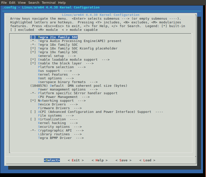
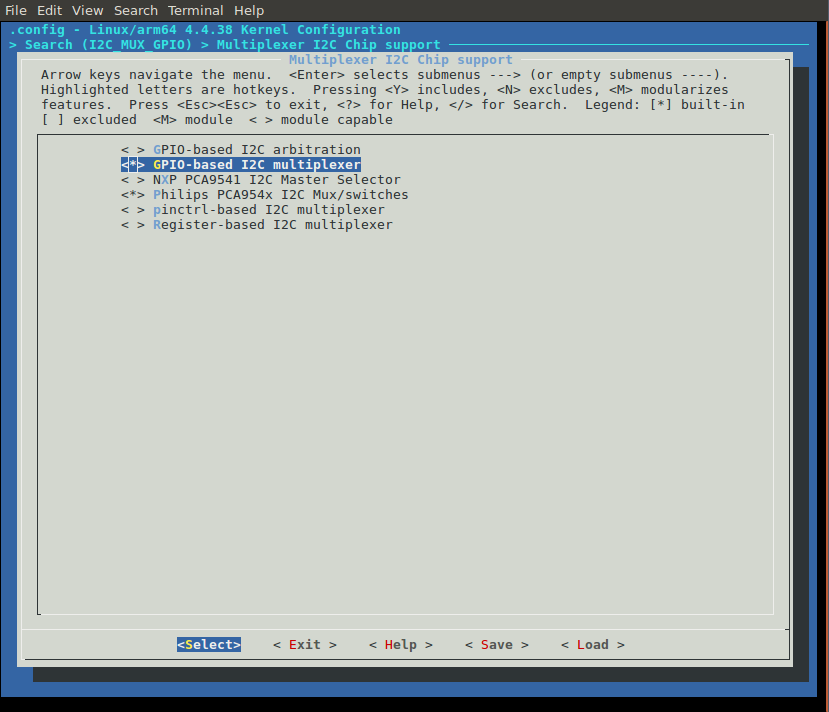
Search for i2c-gpio-mux by pressing ‘/’ then typing ‘I2C_MUX_GPIO’ press enter you should see this:
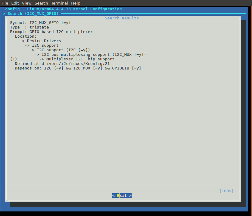
press ‘1’ then spacebar until the selection is a ‘*’ it shold look like this:
Do the same thing by searching for the ‘imx219’.
Use the arrow keys to highlight exit and keep following ‘exit’ until it asks if you would like to save your configuration. Say ‘yes’.
Now you can build the kernel and it should build the device tree source to the correct binary blob.
Modify the IMX219 Driver.
Unfortunately the imx219 driver supplied by NVIDIA is not compatible with the Raspberry Pi so some small modifications need to happen. Among other things the regulator requirements need to be removed and the mode tables need to be changed.
Instead of going through all the changes here is a link to the imx219 driver file and the imx219 mode tables.
Here are the configuration files too:
module tegra186-my-config-a00.dtsi
platform tegra186-my-config-a00.dtsi
(Eventually I’ll move these files to a repo somewhere)
Overwrite the imx219.c and imx219_mode_tbls.h files in the following directory with the ones above:
Linux_for_Tegra/sources/kernel/kernel-4.4/drivers/media/i2cNow rebuild the kernel and it should have the correct drivers.
Userland Tests
After everything is built and burned onto a TX2 and boot up the kernel. You should have three new /dev/videoX entries.
You can run the following command to capture a short video clip:
gst-launch-1.0 -v nvcamerasrc sensor-id=0 fpsRange="30 30" num-buffers=100 ! 'video/x-raw(memory:NVMM), width=(int)1920, height=(int)1080, format=(string)I420, framerate=(fraction)30/1' ! omxh264enc ! 'video/x-h264, width=(int)1920, height=(int)1080, format=(string)I420, framerate=(fraction)30/1' ! h264parse ! qtmux ! filesink location=test.mp4 -eBecause you are running at 30FPS and you capture 100 frames the clip will be 2.33 seconds long. You can play with these values to modify it. You can also switch between different sensors with the ‘sensor-id’ value.
One final note. You may need to refresh your ISP’s image configuration cache in order to ask the kernel to rebuild the ISP configuration for you specific camera.
The cache is located in:
/var/nvidia/nvcam/settingsDelete all these files and restart the TX2 and they should be rebuilt. This value is dependent on the ‘tegra-camera-platform’ configuration.
Just a reminder
I’m not an expert! I might not have done this completely correct, so if you see a problem with this let me know.