Porting NVIDIA TX1 to a New Platform
The NVIDIA TX1 module is an awesome piece of hardware. In the past I’ve designed a couple of boards with SOCs (System on a Chip) including an NVIDIA Tegra 2 and an OMAP4. Both of them were expensive and required a couple of spins to fix small errors. The TX1, on the other hand, simplified the design process by both reducing the SOC interface to one connector and one wide range input voltage range.
The software is another story. Bringing up Linux on a new platform is challenging. It’s a different process for different chips and, on top of that, the process is still evolving.
WARNING: This blog is a way for me to organize my thoughts on this process. I am not an expert so if there are mistakes, please let me know. I think, if these instructions get hammered out we can add this to the Embedded Linux Wiki (TX1)
Essentially the the path from ‘power on’ to CLI involves a lot of disjointed steps that are confusing. Most of this was learned from these three resources:
- Tegra Boot Overview
- Platform Adaptation and Bring-up Guide for TK1
- Developer User Guide Documentation
An overview of what of the whole process consists of:
- Setting up the host computer
- Defining the behaviour of the pins with the Pinmux tool
- Configuring the bootloader
- Configuratin the kernel
- Configure upload tool
- Modify flash tools
- Creating convenience scripts
Setup Your Host
To simplify this discussion I’m going to create a board called quokka and focus on developing for the 24.1 L4T, this may change later when NVIDIA releases newer builds.
I’ll make a directory to do all of this work in:
mkdir -p ~/Projects/tx1echo "Install 32-bit ARM Cross Compiler"
sudo apt-get install gcc-arm-linux-gnueabiMake a directory for the 64-bit toolchain and move into it
mkdir -p aarch-64-toolchain
cd aarch-64-toolchain
Download the toolchain to this new directory and uncompress it
wget https://releases.linaro.org/components/toolchain/binaries/latest-5/aarch64-elf/gcc-linaro-5.3.1-2016.05-x86_64_aarch64-elf.tar.xz
tar xvf gcc-linaro-5.3.1-2016.05-x86_64_aarch64-elf.tar.xz
To simplify things we’ll make a directory where we can store all the output files from the pinmux called ‘pinmux_config’
mkdir -p ~/Projects/tx1/pinmux_configGetting the documentation
In order to set your host computer up to build the kernel and u-boot follow the ‘Getting Started Instructions’ in the developer user guide linked above
Extract the Developer User Guide Documentation to a docs directory
mkdir -p ~/Projects/tx1/docs
cd ~/Projects/tx1/docs
cp ~/Downloads/Tegra_Linux_Driver_Package_Documents_R24.1.tar .
tar xvf Tegra_Linux_Driver_Package_Documents_R24.1.tar
Using a web browser, navigate to the base directory and open up the ‘Start_L4T_Docs.html’
cd ~/Projects/tx1/docs
google-chrome Start_L4t_Docs.html
Navigate to ‘Getting Started’
Get the L4T Development Environment
Theoretically all you should need to port the kernel is the source code for the kernel, uboot as well as a root file system but with every platform there are some helpful tools that are needed. Nvidia provides a great starting point so we’ll need to get the ‘driver package’ to set up our build environment.
There are some parts of the documentation that left me feeling a little confused. Some are small some are big.
Whenever the documentation indicates that you should extract a package just run to the download page and grab it as an example: in the section ‘Extracting Tegra Linux Driver Package’ it just says that I need to extract the source file. I thought ‘should I already have this package?’ You can find all the packages referenced in the Nvidia TX1 Download Page
Download and move the archive from Downloads to your TX1 directory
cd ~/Projects/tx1/
mv ~/Downloads/Tegra210_Linux_R24.1.0_armhf.tbz2 .
tar xvf Tegra210_Linux_R24.1.0_armhf.tbz2
Set up the root file system
Get the rootfs from the download page and move it to the docs directory, then extract the archive as root. This is important because when the rootfs is copied to the TX1 all the permissions of the files will be Root
cd ~/Projects/tx1/Linux_for_Tegra/rootfs
mv ~/Downloads/Tegra_Linux_Sample-Root-Filesystem_R24.1.0_armhf.tbz2 .
sudo tar xf Tegra_Linux_Sample-Root-Filesystem_R24.1.0_armhf.tbz2
rm Tegra_Linux_Sample-Root-Filesystem_R24.1.0_armhf.tbz2
I chose to delete the archive because it’s 600MB and if I left it in that directory it would be copied to the TX1 when flashing.
Get the sources
Get the sources by using the ‘source_sync.h’ script within Linux_for_Tegra directory
Get the Kernel Source
Get the kernel source by navigating to Linux_for_Tegra and run:
cd ~/Projects/tx1/Linux_for_Tegra
./source_sync.sh -k l4t/l4t-r24.1
NOTE: How to select the correct Git Tag
In the ‘Building the NVIDIA kernel’ section there is the following:
To rebuild the kernel
- Get the kernel source by running the source_sync.sh script:
$ ./source_sync.sh -kWhen prompted enter a ‘tag’ name, as provided in the release notes. —Or— Manually sync the sources, as follows:
$ cd <myworkspace>
$ git clone git://nv-tegra.nvidia.com/linux-<lnx_ver>.git kernel_sources
$ cd kernel_sources
$ git checkout <release_tag>
Click on the ‘release_tag’ section and it will display the tag
NOTE OF A NOTE:
After following my notes and trying to create a branch for my board I ran into some issues and found it was better if I just checkout out the branch l4t/l4t-r24.1 instead of tegra-l4t-r24.1
Navigate to the kernel source and create a new branch with the name of your board
navigate to the kernel base and create a new branch called ‘quokka’
cd ~/Projects/tx1/Linux_for_Tegra/sources/kernel_source
git branch quokka
git checkout quokka
Get the U-Boot Source
Similar to the kernel sources get the U-Boot source by navigating to Linux_for_Tegra and runing:
cd ~/Projects/tx1/Linux_for_Tegra
./source_sync.sh -u <release_tag>
NOTE: The tag for u-boot is the same for the kernel
navigate to the u-boot base and create a new branch called ‘quokka’
cd ~/Projects/tx1/Linux_for_Tegra/sources/u-boot_source
git branch quokka
git checkout quokka
Okay we set up the sources, now it’s time to start configuring them
Pinmux
An SOC contains a lot of functionality but there are two major issues with this:
- There may be more functionality within the chip than there are pins so a multiplexer (or selector) is used to allow the designer to select which functions the physical pins exposes.
- The user may want to change the pin location of certain functionality. For example you may want UART TX and RX to be located on a different set of pins due to layout issues or because you want the original pins to be used for something else.
It is challenging to modify the pin configuration. It seems that every manufacturer has a different mechanism to do this. Some require the developer to select and verify that all functionality of the pin multiplexer is correctly implemented by hand. This is tuff because a mistake can cause physical damage or a difficult to detect software error. TI has a whole application dedicated to this: Pin Mux Tool Nvidia, uses a simple, yet effective, Excel Pin Mux Sheet along with some command line scripts: The pinmux selection process is as follows (More details below):
- Download the Pinmux Spreadsheet: Pinmux Spreadsheet
- Modify the table so that the functions that you want are exposed on the pins you want.
- If there are no errors export the sheet to a csv file.
- Feed this csv file into the csv-to-board.py to generate an pinmux configuration file that is specifically for your board.
- Generate a pinmux header file for your bootloader.
- Using the Spreadsheet generate the DT file. This will be used during the hand off from bootloader to kernel.
Detailed Pinmux Flow
Edit Pinmux Spreadsheet
After downloading the pinmux spreadsheet open the spreadsheet with Microsoft Excel. I tried to use Office Libre Spreadsheet but the internal macros didn’t work that well and all I got were a bunch of errors on the page.
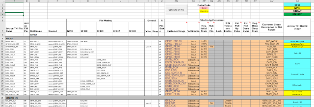
It’s a little hard to see but on the left is the name of the pin and ball, there are columns describing the possible functions of the pins and the pins. As an example pin H1 names DAP1_DOUT can be configured in the following way:
- Left disconnected (unused)
- A GPIO called GPIO3_PB.02
- I2S Serial Data Out.
All orange cells are customizable. You make your selecton under ‘Customer Usage’
If your pinmux combination leads to an error the cells in questions will turn red and you’ll see something like this:
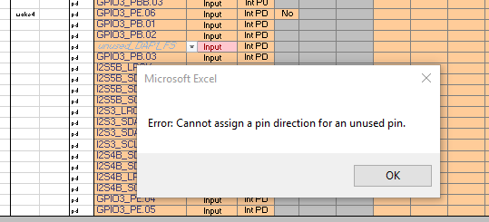
Otherwise if everything is fine then all the editable regions will stay orange.
Save to CSV
After you have made your changes to pinmux save the file as a CSV file called: ‘quokka-2180.csv’
Save the kernel pinmux dtsi file
The spreadsheet will also generate a dtsi file that will be read by the kernel later on so we need to copy it to our ‘pinmux_config’ folder we created earlier
cd ~/Projects/tx1/pinmux_config
cp ~/Downloads/tegra210-quokka-pinmux.dtsi .
Get the NVIDIA Pinmux Tools
Now that you have the csv of the pinmux configuration use the nvidia pinmux tools found at github:
cd ~/Projects/tx1
git clone https://github.com/NVIDIA/tegra-pinmux-scripts.git
You will need to modify the ‘csv-to-board.py’ file
cd ~/Projects/tx1/tegra-pinmux-scripts
vim csv-to-board.py
Add support for our board:
supported_boards = {
    'e2220-1170': {
        # T210_customer_pinmux.xlsm worksheet [elided] (0-based rsvd)

        'filename': 'csv/e2220-1170.csv',
        'rsvd_base': 0,
        'soc': 'tegra210',
    },
    'jetson-tk1': {
        # Jetson_TK1_customer_pinmux.xlsm worksheet Jetson TK1 Configuration (1-based rsvd) from:

        # https://developer.nvidia.com/hardware-design-and-development

        'filename': 'csv/jetson-tk1.csv',
        'rsvd_base': 1,
        'soc': 'tegra124',
    },
    'norrin': {
        # PM370_T124_customer_pinmux_1.1.xlsm worksheet Customer_Configuration (0-based rsvd)

        'filename': 'nv-internal-data/PM370_T124_customer_pinmux_1.1.csv',
        'rsvd_base': 0,
        'soc': 'tegra124',
    },
    'p2371-0000': {
        # T210_customer_pinmux.xlsm worksheet [elided] Configuration (0-based rsvd)

        'filename': 'csv/p2371-0000.csv',
        'rsvd_base': 0,
        'soc': 'tegra210',
    },
    'p2371-2180': {
        # T210_customer_pinmux.xlsm worksheet [elided] Configuration (0-based rsvd)

        'filename': 'csv/p2371-2180.csv',
        'rsvd_base': 0,
        'soc': 'tegra210',
    },
    'quokka-2180': {
        # Custom board

        'filename': '../pinmux_config/quokka-2180.csv',
        'rsvd_base': 0,
        'soc': 'tegra210',
    },
    'p2571': {
        # T210_customer_pinmux.xlsm worksheet [elided] Configuration (0-based rsvd)

        'filename': 'csv/p2571.csv',
        'rsvd_base': 0,
        'soc': 'tegra210',
    },
    'tegra210-smaug': {
        # erista_customer_pinmux_v04_0420.xlsm

        'filename': 'csv/tegra210-smaug-v04_0420.csv',
        'rsvd_base': 0,
        'soc': 'tegra210',
    },
    'venice2': {
        # Venice2_T124_customer_pinmux_based_on_P4_rev47_2013-07-12.xlsm worksheet Customer_Configuration (0-based rsvd)

        'filename': 'nv-internal-data/Venice2_T124_customer_pinmux_based_on_P4_rev47_2013-07-12.csv',
        'rsvd_base': 0,
        'soc': 'tegra124',
    },
}
Move your csv file to where it’s specified in the csv-to-board location
cd ~/Projects/tx1/pinmux_config
mv ~/Downloads/quokka-2180.csv .
Generate A Board File
You can now generate a board file. This is an intermediate pinmux format that other scripting tools will use to generate the specific files for the bootloader and the kernel.
cd ~/Projects/tx1/tegra-pinmux-scripts
./csv-to-board.py quokka-2180
The board file will be in ~/Projects/tx1/tegra-pinmux-script/configs/quokka-2180.board
Here is the beginning of the file:
soc = 'tegra210'

pins = (
    #pin,                    mux,          gpio_init, pull,   tri,   e_inp, od,    e_io_hv
    ('aud_mclk_pbb0',        None,         'in',      'up',   False, True,  False, False),
    ('gpio_x1_aud_pbb3',     None,         'in',      'up',   False, True,  False, False),
    ('pe6',                  None,         'in',      'down', False, True,  False, False),
    ('dap1_din_pb1',         None,         'in',      'down', False, True,  False, False),
    ('dap1_dout_pb2',        None,         'in',      'down', False, True,  False, False),
    ('dap1_fs_pb0',          None,         'in',      'down', False, True,  False, False),
...
Generate U-Boot Headerfiles
Using the board file you can create a header file to be used with U-Boot.
The syntax to generate the header file is as follows:
cd ~/Projects/tx1/tegra-pinmux-scripts
./board-to-uboot.py quokka-2180
This will output the header file to stdout so you will need to redirect the output to a file. For reasons I’ll explain later call this new file: g-quokka-2180.h
cd tegra-pinmux-scripts
./board-to-uboot.py quokka-2180 > pinmux-quokka-2180.h
If your interested the file looks like this:
/*
 * Copyright (c) 2016, NVIDIA CORPORATION. All rights reserved.
 *
 * SPDX-License-Identifier: GPL-2.0+
 */

/*
 * THIS FILE IS AUTO-GENERATED - DO NOT EDIT!
 *
 * To generate this file, use the tegra-pinmux-scripts tool available from
 * https://github.com/NVIDIA/tegra-pinmux-scripts
 * Run "board-to-uboot.py p2371-2180".
 */

#ifndef _PINMUX_CONFIG_P2371_2180_H_
#define _PINMUX_CONFIG_P2371_2180_H_

#define GPIO_INIT(_gpio, _init)    \
 {      \
  .gpio = GPIO_P##_gpio,  \
  .init = TEGRA_GPIO_INIT_##_init, \
 }

static const struct tegra_gpio_config p2371_2180_gpio_inits[] = {
 /*        gpio, init_val */
 GPIO_INIT(A5,   IN),
 GPIO_INIT(B0,   IN),
 GPIO_INIT(B1,   IN),
 GPIO_INIT(B2,   IN),
 GPIO_INIT(B3,   IN),
 GPIO_INIT(C0,   IN),
 GPIO_INIT(C1,   IN),
 GPIO_INIT(C2,   IN),
 GPIO_INIT(C3,   IN),
...
Bootloaders
There are two stages of bootloading in the TX1 the following section discusses the first stage bootloader but it’s not required for users to understand this step for porting and can skip to U-Boot below.
First Stage Bootloader
This configuration is not accessible by users but is here for users to understand the bootup process.
The X1 SOC on the TX1 actually contains two processor.
- Boot Processor called Boot and Power Management Processor (BPMP) it can also be called: Audio Video Processor (AVP) or sometimes Co-Processor (COP).
- Main Processor called CCPLEX The Boot processor prepares everything before starting then handing off control to the main processor.
When the SOC turns on the boot processor wakes up and reads the state of both the fuses and straps.
- Straps: These are actual pins that are read by the chip when the board turns on. This is easy to modify by simply adding external resistors or shorts to the TX1 Module pins.
- Fuses: Internally configuration bits that usually is set by the manufacturer. These are more challenging to modify If no valid configuration is detected the chip enters USB Recovery mode in order to allow users to fix the problem. This is what happens when the TX1 Devboard is configured for force recovery mode.
Boot Peripheral
The fuses and straps tell the boot processor which peripheral (eMMC, SPI Flash, etc…) contains the boot information.
Boot Configuration Table
The first piece of data read is the Boot Configuration Table
The boot processor needs to be configured and the BCT (Boot Configuration Table) is what does this. This BCT is not externally accessible but it’s a good idea to know how this works. You can read about the details of the BCT here but basically this is the first configuration file that the TX1 sees. It helps the boot processor perform the following functions:
- Updates the memory controller with less conservative values to loading/processing can be done faster.
- Loads the seconds stage bootloader (U-Boot) from memory and validates the bootloader. Jumps to bootloader entry point and starts executing.
Second Stage Bootloader (U-Boot)
U-Boot is the tool that prepares the SOC for the kernel. In order to prepare it for our board we need to modify u-boot.
At a high level we’ll
- Create a configuration file for U-Boot
- Create a Device Tree Source (DTS) to describe our hardware to U-Boot
- Add a board directory to expose board specific functions and configurations
- Modify Kconfig for the SOC to recognize our board
- Create a build tool configuration file to describe how to build our hardware to the build tools
Add a board configuration file (U-Boot Configuration File)
Add new board configuration header by copying the NVIDIA TX1 Development Board
cd ~/Projects/tx1/Linux_for_Tegra/sources/u-boot_source/include/configs
cp p2371-2180.h quokka-2180.h
Modify some values to help identify your board when u-boot is booting:
cd ~/Projects/tx1/Linux_for_Tegra/sources/u-boot_source/include/configs
vim quokka-2180.h
Change the high level configuration options from this
/* High-level configuration options */
#define V_PROMPT			"Tegra210 (P2371-2180) # "
#define CONFIG_TEGRA_BOARD_STRING	"NVIDIA P2371-2180"
to this
/* High-level configuration options */
#define V_PROMPT			"Tegra210 (quokka-2180) # "
#define CONFIG_TEGRA_BOARD_STRING	"NVIDIA QUOKKA-2180"
Add a DTS (Hardware Description File)
A DTS or (Device Tree Source) describes the hardware of your platform, it’s not a configuration file as much as it simply describes what exists. The idea is that the DTS is OS Independent. This file will allow us to enable and disable portions of the TX1 Module. Things that distinguish quokka from other boards.
Similar to the board configuration file copy the NVIDIA TX1 Development Board dts file to ‘quokka-2180.dts’
cd ~/Projects/tx1/Linux_for_Tegra/sources/u-boot_source/arch/arm/dts
cp tegra210-p2371-2180.dts tegra210-quokka-2180.dts
Modify some values to help identify your board when u-boot is booting:
cd ~/Projects/tx1/Linux_for_Tegra/sources/u-boot_source/arch/arm/dts
vim tegra210-quokka-2180.dts
Change this:
	model = "NVIDIA P2371-2180";
	compatible = "nvidia,p2371-2180", "nvidia,tegra210";
To this:
	model = "NVIDIA QUOKKA-2180";
	compatible = "nvidia,quokka-2180", "nvidia,tegra210";
Similar to normal makefiles we’ll need to let the local Makefile know that this new device tree source file is here and needs to be compiled.
Go to the DTS Makefile and edit it:
cd ~/Projects/tx1/Linux_for_Tegra/sources/u-boot_source/arch/arm/dts
vim Makefile
Modify this:
dtb-$(CONFIG_TEGRA) += tegra20-harmony.dtb \
	tegra20-medcom-wide.dtb \
	tegra20-paz00.dtb \
	tegra20-plutux.dtb \
	tegra20-seaboard.dtb \
	tegra20-tec.dtb \
	tegra20-trimslice.dtb \
	tegra20-ventana.dtb \
	tegra20-whistler.dtb \
	tegra20-colibri.dtb \
	tegra30-apalis.dtb \
	tegra30-beaver.dtb \
	tegra30-cardhu.dtb \
	tegra30-colibri.dtb \
	tegra30-tec-ng.dtb \
	tegra114-dalmore.dtb \
	tegra124-jetson-tk1.dtb \
	tegra124-nyan-big.dtb \
	tegra124-venice2.dtb \
	tegra210-e2220-1170.dtb \
	tegra210-p2371-0000.dtb \
	tegra210-p2371-2180.dtb \
	tegra210-p2571.dtb
dtb-$(CONFIG_ARCH_UNIPHIER) += \
	uniphier-ph1-sld3-ref.dtb \
To this:
dtb-$(CONFIG_TEGRA) += tegra20-harmony.dtb \
	tegra20-medcom-wide.dtb \
	tegra20-paz00.dtb \
	tegra20-plutux.dtb \
	tegra20-seaboard.dtb \
	tegra20-tec.dtb \
	tegra20-trimslice.dtb \
	tegra20-ventana.dtb \
	tegra20-whistler.dtb \
	tegra20-colibri.dtb \
	tegra30-apalis.dtb \
	tegra30-beaver.dtb \
	tegra30-cardhu.dtb \
	tegra30-colibri.dtb \
	tegra30-tec-ng.dtb \
	tegra114-dalmore.dtb \
	tegra124-jetson-tk1.dtb \
	tegra124-nyan-big.dtb \
	tegra124-venice2.dtb \
	tegra210-e2220-1170.dtb \
	tegra210-p2371-0000.dtb \
	tegra210-p2371-2180.dtb \
	tegra210-quokka-2180.dtb \
	tegra210-p2571.dtb
dtb-$(CONFIG_ARCH_UNIPHIER) += \
	uniphier-ph1-sld3-ref.dtb \
Add a unique board directory
Our board may need unique device descriptors and functions that are different from other boards. Specifically this is a great location for the header file we made with the tegra pinmux tools at the beginning.
Similar to before we’ll copy the p23710-2180 directory and modify it to point to describe our board.
cd ~/Projects/tx1/Linux_for_Tegra/sources/u-boot_source/board/nvidia
cp -a p2371-2180 quokka-2180
Inside this new directory are a some files to modify
- MAINTAINERS
- Makefile
- Kconfig Build Configuration File
- p2371-2180.c Board Specific Functions
- g-p2371-2180.h Our Pinmux Configuration File
First Modify the MAINTINERS and add yourself to it
Instead of modifying every single file we can use sed to do some of this work for us
cd ~/Projects/tx1/Linux_for_Tegra/sources/u-boot_source/board/nvidia/quokka-2180

echo "Change the board c file name to reflect our project filename"
mv p2371-2180.c quokka-2180.c

echo "Remove the current pinmux file with our pinmux file"
rm pinmux-config-p2371-2180.h
mv ../../../../../../pinmux-config-quokka-2180.h .

echo "use sed to replace the reference to the previous board pinmux with our board pinmux"
grep -rIl 'pinmux-config-p2371-2180.h' | xargs sed -i 's/pinmux-config-p2371-2180.h/pinmux-config-quokka2180.h/g'

echo "Use grep to find the files with a certain string and use sed to replace the string with our board"
grep -ril 'TARGET_P2371_2180' | xargs sed -i 's/TARGET_P2371_2180/TARGET_QUOKKA_2180/g'
grep -rIl 'p2371-2180' | xargs sed -i 's/p2371-2180/quokka-2180/g'
grep -rIl 'p2371_2180' | xargs sed -i 's/p2371_2180/quokka_2180/g'
grep -rIl 'P2371_2180' | xargs sed -i 's/P2371_2180/QUOKKA_2180/g'
cd ~/Projects/tx1/tegra-pinmux-scripts
./board-to-uboot.py quokka-2180 > ~/Projects/tx1/Linux_for_Tegra/sources/u-boot_source/board/nvidia/quokka-2180/pinmux-config-quokka-2180.hModify Kconfig for the SOC
When selecting an SOC like the Tegra 210 the build configuration allows you to select certain compatible boards. We need to modify that configuration script to allow our board to be selected.
Go to the SOC folder and modify the Kconfig file
cd ~/Projects/tx1/Linux_for_Tegra/sources/u-boot_source/arch/arm/mach-tegra/tegra210
vim Kconfig
Modify the file to tell the build system we have another option for the board
from this
config TARGET_P2371_2180
	bool "NVIDIA Tegra210 P2371-2180 board"
	help
	  P2371-2180 is a P2180 CPU board married to a P2597 I/O board. The
	  combination contains SoC, DRAM, eMMC, SD card slot, HDMI, USB
	  micro-B port, Ethernet via USB3, USB3 host port, SATA, PCIe, and
	  two GPIO expansion headers.
to this
config TARGET_P2371_2180
	bool "NVIDIA Tegra210 P2371-2180 board"
	help
	  P2371-2180 is a P2180 CPU board married to a P2597 I/O board. The
	  combination contains SoC, DRAM, eMMC, SD card slot, HDMI, USB
	  micro-B port, Ethernet via USB3, USB3 host port, SATA, PCIe, and
	  two GPIO expansion headers.

config TARGET_QUOKKA_2180
	bool "CD Tegra210 QUOKKA-2180 board"
	help
	  QUOKKA-2180 is a P2180 CPU board married to an adorable IO Board
    called Quokka
Also at the bottom of the file we need to tell the build tool what Kconfig files to include our board Kconfig file
in the same file modify this
source "board/nvidia/e2220-1170/Kconfig"
source "board/nvidia/p2371-0000/Kconfig"
source "board/nvidia/p2371-2180/Kconfig"
source "board/nvidia/p2571/Kconfig"
To this:
source "board/nvidia/e2220-1170/Kconfig"
source "board/nvidia/p2371-0000/Kconfig"
source "board/nvidia/p2371-2180/Kconfig"
source "board/nvidia/quokka-2180/Kconfig"
source "board/nvidia/p2571/Kconfig"
Add a configuration file for the Build tool
Now we need to tell the Build Tool how to build our board so we’ll need to add a build configuration file
Go to the u-boot build configuration directory and copy the defconfig for p2371-2180 to our board:
cd ~/Projects/tx1/Linux_for_Tegra/sources/u-boot_source/configs
cp p2371-2180_defconfig quokka-2180_defconfig
Edit this configuration file to point to our board instead of p2371-2180
cd ~/Projects/tx1/Linux_for_Tegra/sources/u-boot_source/configs
vim quokka-2180_defconfig
Modify this:
CONFIG_TARGET_P2371_2180=y
CONFIG_DEFAULT_DEVICE_TREE="tegra210-p2371-2180"
To this:
CONFIG_TARGET_QUOKKA_2180=y
CONFIG_DEFAULT_DEVICE_TREE="tegra210-quokka-2180"
Build U-Boot
Before you start modifying u-boot it’s a good idea to build it so we know we made it through a build instead of configuring a terminal with all the build tools here is a simple script to build uboot
#! /bin/bash


"Setting Environmental Variables..."
export ARCH=arm64
export CROSS32CC=arm-linux-gnueabi-gcc
export TX_BASE_DIR=${PWD}
export CROSS_COMPILE=$TX_BASE_DIR/aarch-64-toolchain/gcc-linaro-5.3.1-2016.05-x86_64_aarch64-elf/bin/aarch64-elf-
export TEGRA_UBOOT_OUT=$TX_BASE_DIR/Linux_for_Tegra/bootloader/t210ref/quokka-2180
export ROOTFS_PATH=$TX_BASE_DIR/Linux_for_Tegra/rootfs
export UBOOT_SOURCE=$TX_BASE_DIR/Linux_for_Tegra/sources/u-boot_source


COMMAND="BUILD"

#Parse the Inputs

echo "Key: $1"

while [[ $# > 0 ]]
do
key="$1"

case $key in
    -r|--rebuild)
    COMMAND="REBUILD"
    shift # past argument

    ;;
    -m|--menu)
    COMMAND="MENU"
    shift # past argument

    ;;
    *)
    # unknown option

    ;;
esac
shift
done

echo "Finished parsing inputs"

cd $UBOOT_SOURCE

if [ "$COMMAND" == "BUILD" ]; then
  echo "Build"
  make O=$TEGRA_UBOOT_OUT -j4
fi
if [ "$COMMAND" == "REBUILD" ]; then
  echo "Re-Build"
  make mrproper
  make O=$TEGRA_UBOOT_OUT -j4 distclean
  make O=$TEGRA_UBOOT_OUT -j4 mit-uav-reva_defconfig
  make O=$TEGRA_UBOOT_OUT -j4
fi
if [ "$COMMAND" == "MENU" ]; then
  echo "Menu Config"
  make O=$TEGRA_UBOOT_OUT -j4 menuconfig
fi
To use this copy the content of the cell above into a file called ‘build_uboot.sh’ inside the ~/Projects/tx1 directory modify it to allow execution.
cd ~/Projects/tx1
chmod +x ./build_uboot.sh
First Build: Rebuild the project in order to pick up the quokka-2180_config
cd ~/Projects/tx1
echo "First Build"
./build_uboot.sh --rebuild
After a successful build you won’t need to use the ‘–rebuild’ command simply use ‘build_uboot.sh’ and it will build much faster
cd ~/Projects/tx1
echo "Normal Build"
./build_uboot.sh
If you would like to use menuconfig to visually configure the build you can use the –menu flag
cd ~/Projects/tx1
echo "Normal Build"
./build_uboot.sh --menu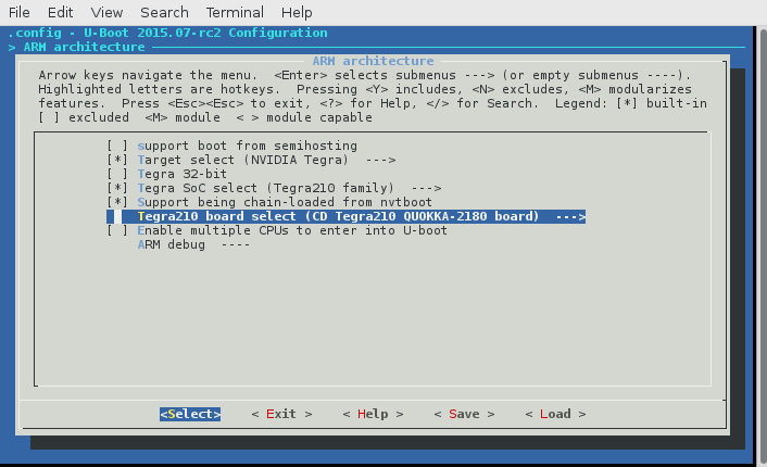
Kernel
Configuring the kernel is less involved than u-boot. The main portions to configure are:
- Modify the device tree sources dts and dtsi files for our board
- Update the build tools to understand our board
- Add a configuration header file for our board
- Incorporate our board into the build tools
Modify the Device Tree Sources
Similar to U-Boot the Device Tree Sources describes the peripherals of the board. Unfortunately the DTS defined in the kernel and u-boot are not compatible so we need to go through the board adaptation process again.
navigate to the dts files for the tegra210 and copy the TX1 devboard dts to a Quokka version
cd ~/Projects/tx1/Linux_for_Tegra/sources/kernel_source/arch/arm64/boot/dts
cp tegra210-jetson-cv-base-p2597-2180-a00.dts tegra210-jetson-cv-base-quokka-2180-a00.dts
add the dtsi file created from the pinmux tool earlier to ‘tegra210-platform’ directory
cd ~/Projects/tx1/pinmux_config
cp tegra210-quokka-pinmux.dtsi ~/Projects/tx1/Linux_for_Tegra/sources/kernel_source/arch/arm64/boot/dts/tegra210-platforms/
Create a new DTS that will allow us to override the base implementation copy tegra210-jetson-tx1-p2597-2180-a01-devkit.dts to tegra210-quokka-2180-a01.dts
cd ~/Projects/tx1/Linux_for_Tegra/sources/kernel_source/arch/arm64/boot/dts
cp tegra210-jetson-tx1-p2597-2180-a01-devkit.dts tegra210-quokka-2180-a01.dts
The DTS file describes the hardware, we can use this to
- Modify hardware configuration
- Distinguish our boards from others by using a different board id
- point to the correct pinmux dts include file
cd ~/Projects/tx1/Linux_for_Tegra/sources/kernel_source/arch/arm64/boot/dts
vim tegra210-jetson-cv-base-quokka-2180-a00.dts
Change this
...
#include "tegra210-platforms/tegra210-audio.dtsi"
#include "tegra210-platforms/tegra210-jetson-cv-power-tree-p2597-2180-a00.dtsi"
#include "tegra210-platforms/tegra210-jetson-cv-pinmux-p2597-2180-a00.dtsi"
#include "tegra210-platforms/tegra210-jetson-cv-sdmmc-drv-p2597-2180-a00.dtsi"
#include "tegra210-platforms/tegra210-jetson-cv-prods.dtsi"
...
To this
...
#include "tegra210-platforms/tegra210-audio.dtsi"
#include "tegra210-platforms/tegra210-jetson-cv-power-tree-p2597-2180-a00.dtsi"
#include "tegra210-platforms/tegra210-quokka-pinmux.dtsi"
#include "tegra210-platforms/tegra210-jetson-cv-sdmmc-drv-p2597-2180-a00.dtsi"
#include "tegra210-platforms/tegra210-jetson-cv-prods.dtsi"
...
Change this
	nvidia,boardids = "2597:2180:A0";
	nvidia,proc-boardid = "2597:2180:A0";
	nvidia,pmu-boardid = "2597:2180:A0";
	#address-cells = <2>;
	#size-cells = <2>;
To this
	nvidia,boardids = "C594:2180:A0";
	nvidia,proc-boardid = "C594:2180:A0";
	nvidia,pmu-boardid = "C594:2180:A0";
	#address-cells = <2>;
	#size-cells = <2>;
Tell the build tools to build compile our new dts
cd ~/Projects/tx1/Linux_for_Tegra/sources/kernel_source/arch/arm64/boot/dts
vim Makefile
Change this
dtb-$(CONFIG_ARCH_TEGRA_21x_SOC) += tegra210-loki-e-e2581-0131-a01-00.dtb
dtb-$(CONFIG_ARCH_TEGRA_21x_SOC) += tegra210-jetson-cv-base-p2597-2180-a00.dtb
dtb-$(CONFIG_ARCH_TEGRA_21x_SOC) += tegra210-jetson-cv-p2597-2180-a00.dtb
dtb-$(CONFIG_ARCH_TEGRA_21x_SOC) += tegra210-jetson-tx1-p2597-2180-a01-devkit.dtb
dtb-$(CONFIG_ARCH_TEGRA_21x_SOC) += tegra210-jetson-tx1-p2597-2180-a02-devkit-24x7.dtb
To this
dtb-$(CONFIG_ARCH_TEGRA_21x_SOC) += tegra210-loki-e-e2581-0131-a01-00.dtb
dtb-$(CONFIG_ARCH_TEGRA_21x_SOC) += tegra210-jetson-cv-base-p2597-2180-a00.dtb
dtb-$(CONFIG_ARCH_TEGRA_21x_SOC) += tegra210-jetson-cv-base-quokka-2180-a00.dtb
dtb-$(CONFIG_ARCH_TEGRA_21x_SOC) += tegra210-jetson-cv-p2597-2180-a00.dtb
dtb-$(CONFIG_ARCH_TEGRA_21x_SOC) += tegra210-jetson-tx1-p2597-2180-a01-devkit.dtb
dtb-$(CONFIG_ARCH_TEGRA_21x_SOC) += tegra210-jetson-tx1-p2597-2180-a02-devkit-24x7.dtb
Modify Flash Tools
The flash tools are configured to install the bootloader and kernel to the board, in order to adapt our board, we’ll do the following
- Copy and modify existing extlinux.conf* files to describe medium (sdmmc, usb, etc…) dependent boot configuration to the bootloader
- Copy and modify the medium independent flash configuration file: quokka-2180.conf
- Create a board configuration file
Adapt extlinux
extlinux.conf.* files configures how the bootloader loads up the kernel, it describes where the kernel is stored (emmc, SD Card, USB Stick, Network). It is possible for U-Boot to present the user with multiple options when booting the kernel.
Specifically the extlinux files describe:
- A menu title to help the user select options.
- The kernel command line arguments that will be fed into the kernel upon boot.
- Where the kernel is loaded on the medium.
- What device tree binary to load with the kernel
For the TX1 Module the extlinux.conf.emmc can be copied from the p2371-2180-devkit directory to quokka-2180 because the module, which is common between the two boards, has the same EMMC.
Copy and edit the extlinux.conf.emmc
cd ~/Projects/tx1/Linux_for_Tegra/bootloader/t210ref
cp p2371-2180-devkit/extlinux.conf.emmc quokka-2180/
vim quokka-2180/extlinux.conf.emmc
You will need to change the title as well as the dtb to point to our quokka dtb
Change this:
TIMEOUT 30
DEFAULT primary

MENU TITLE p2371-2180 eMMC boot options

LABEL primary
      MENU LABEL primary kernel
      LINUX /boot/Image
      FDT /boot/tegra210-jetson-tx1-p2597-2180-a01-devkit.dtb
...
To this:
TIMEOUT 30
DEFAULT primary

MENU TITLE quokka-2180 eMMC boot options

LABEL primary
      MENU LABEL primary kernel
      LINUX /boot/Image
			FDT /boot/tegra210-quokka-2180-a01.dtb
...
Create the board configuration XML file
The board configuration file populates constants that are board depenedent. These constants describe the ID of the processor the display and the power management unit.
//XXX I’m not sure exactly what this is for?? I would venture to guess that these values are loaded directly into the boot medium to be read by the bootloader.
Copy the board_config_p2597-defkit.xml to a new board_config_quokka.xml
cd ~/Projects/tx1/Linux_for_Tegra/bootloader/t210ref/cfg
cp board_config_p2597-devkit.xml board_config_quokka.xml
Create a flash configuration file for the flash tool
The flash tool needs to know how to write all of the various above configurtions we wrote to the appropriate boot device. Two things are needed. A boot medium such as EMMC or SD Card and a .conf file to describe the medium independent files to write.
copy and edit the new quokka-2180.conf file:
cd ~/Projects/tx1/Linux_for_Tegra
cp p2371-2180-devkit.conf quokka-2180.conf
vim quokka-2180.conf
we need to change the following properties:
- SYSBOOTFILE
- DTB_FILE
- BOOTLOADER
- BCFFILE
Change the following properties
From this
SYSBOOTFILE=p2371-2180-devkit/extlinux.conf;
DTB_FILE=tegra210-jetson-tx1-p2597-2180-a01-devkit.dtb
BOOTLOADER="bootloader/${target_board}/p2371-2180/u-boot-dtb.bin";
BCFFILE="bootloader/${target_board}/cfg/board_config_p2597-devkit.xml";
To this
SYSBOOTFILE=quokka-2180/extlinux.conf;
DTB_FILE=tegra210-quokka-2180-a01.dtb
BOOTLOADER="bootloader/${target_board}/quokka-2180/u-boot-dtb.bin";
BCFFILE="bootloader/${target_board}/cfg/board_config_quokka.xml";
Convenient build scripts
There is a lot of one time configuration that is required for porting a board but after all this heavy lifting is done the rest of the time you will be making small changes to the pin configuration, bootloader and kernel rebuilding and downloading.
When I first started working with Linux for Tegra I would configure a terminal for bootloader builds, one for kernel builds and another for uploads. After a while I got lazy and wrote these scripts: